Support
Start here
Basics
Work through these before calling support. Most faults clear with a reset once the cause behind them is dealt with — both reset procedures are at the end.
Blink codes · Fault codes
Fault handling
The same faults, shown two ways — read the one that matches your inverter’s display. Both point at the reset procedures below.
| Blink pattern | What it means | What to do |
|---|---|---|
| 1 blink Once every four seconds | Low Battery. Battery voltage fell below the low-battery cut-out (LBCO) setpoint. |
|
| 2 blinks Twice every four seconds | High Battery. Battery voltage rose above the high-battery cut-out setpoint for your model. |
|
| 3 blinks Three times every four seconds | Overtemp. The internal FETs and/or transformer went past their operating temperature — transformer above 117 °C / 243 °F, FETs above 90 °C / 194 °F. |
|
| 4 blinks Four times every four seconds | AC Overload. The load on the AC output is larger than the inverter’s capacity. |
After each attempt, perform a soft reset and press the on/off pushbutton to turn the inverter back on. |
| 5 blinks Five times every four seconds | Internal Bridge, Internal Charger, Internal NTC, Internal Relay. An internal fault that isn’t one of the four above. A remote with a text display names which circuit tripped; a single LED can’t, so all four arrive as one code here. | Perform a hard reset. If the fault stays or comes back, the inverter needs repair at an authorized service center. |
A quick-reference list, not the complete fault table. Your inverter’s owner’s manual carries the full set, and the cut-out values, for your model.
| Matches your search | Fault message | What it means | What to do |
|---|---|---|---|
| AC Backfeed | AC voltage from an external source was detected on the inverter’s AC output, so the inverter shut down. |
Then perform a soft reset. |
|
| AC Overload AC Ovrld | The load on the AC output is larger than the inverter’s capacity. |
After each attempt, perform a soft reset and press the on/off pushbutton to turn the inverter back on. |
|
| Breaker Tripped Brk Trip | The inverter/charger’s AC input breaker opened because too much current was flowing through to the AC loads. | Reduce the AC loads so the current stays under the input breaker’s rating, then push the AC input breaker in to reset and resume operation. | |
| Dead Batt Charge Dead Bat | Before charging began, the inverter measured very low voltage at its DC terminals — under 7 V on a 12 V system, 14 V on 24 V, or 28 V on 48 V. |
|
|
| FET Overload FetOvrld | The internal FETs (field effect transistors) heated up too fast — usually a load or short on the AC output larger than the inverter can handle. |
|
|
| High AC Volts High VAC | The AC input voltage is higher than normal while charging. | Bring the AC source under 130 V (on a 120 VAC system). Disconnect the source from the AC input and perform a soft reset. Some generators show high AC voltage on startup. | |
| High Battery High Bat | Battery voltage went above the high-battery cut-out — over 16.0 V on 12 V ME/RD models, 16.9 V on 12 V MS models, 32.0 V on 24 V ME/RD, 33.8 V on 24 V MS, or 67.6 V on 48 V models. |
|
|
| High Batt Temp HiBaTemp | The battery temperature sensor (BTS) read above 54 °C / 129 °F, and the inverter/charger shut down. |
|
|
| Internal Bridge Bridge | The inverter shut down to protect its internal FET bridge circuit. | Perform a hard reset. If the fault stays or comes back, the inverter needs repair at an authorized service center. | |
| Internal Charger CHARGER | The inverter shut down to protect its internal charger circuit. | Perform a hard reset. If the fault stays or comes back, the inverter needs repair at an authorized service center. | |
| Internal NTC NTC Snsr | The inverter shut down to protect its internal NTC (negative temperature coefficient) circuit. | Perform a hard reset. If the fault stays or comes back, the inverter needs repair at an authorized service center. | |
| Internal Relay IntRelay | The inverter shut down to protect its internal relay transfer circuit. | Perform a hard reset. If the fault stays or comes back, the inverter needs repair at an authorized service center. | |
| Low Battery Low Batt | Battery voltage fell below the low-battery cut-out (LBCO) setpoint. |
|
|
| No Inverter Comm No Comm | The remote isn’t receiving anything from the inverter. |
|
|
| Overcurrent OvrCurnt · DC Overload | The inverter shut down to protect internal components from overcurrent — usually too much load on the AC output. |
After each attempt, press the on/off pushbutton to turn the inverter back on. |
|
| Overtemp | The internal FETs and/or transformer went past their operating temperature — transformer above 117 °C / 243 °F, FETs above 90 °C / 194 °F. |
|
|
| Stack Clock Fault Stak CLK | A stacking cable problem, or one inverter in a stacked system is losing sync with the other. |
Perform a hard reset after each attempt. |
|
| Stack Mode Fault StakMode | A problem with another inverter in a stacked system — usually they aren’t all in the same mode (charging vs inverting). | Press the port button to see what each inverter’s remote is showing. All of them should be on, fault-free, and — in charge mode — have AC power at their inputs. | |
| Stack Phase Fault StckPhas | The inverter outputs aren’t in sync, or aren’t 180° out of phase with each other. |
|
|
| Stuck Relay StkRelay | The internal relay should be switching between charging / AC pass-through and inverting, but isn’t. | Perform a hard reset. If the fault stays or comes back, the inverter needs repair at an authorized service center. | |
| Tfmr Overtemp TfmrTemp | The internal transformer is above 118 °C / 244 °F. |
Once the temperature has come down, perform a soft reset. |
|
| Unknown Fault ## Fault XX | The inverter reported a fault the remote doesn’t recognize. |
|
No rows match that search.
A quick-reference list, not the complete fault table. Your inverter’s owner’s manual carries the full set for your model.
Clears most faults
Soft reset
Turn off AC power to the inverter first. Skipping this step can damage the unit.
- Turn off AC power to the inverter.
- Press and hold the power on/off pushbutton for about 15 seconds, until the charging/inverting status LED comes on and flashes rapidly. The pushbutton is a light momentary switch — press gently, or it can break.
- Release the pushbutton once the rapid flashing starts. The status LED goes out.
- Press the on/off pushbutton to turn the inverter back on.
If the fault doesn’t clear, perform a hard reset. Your owner’s manual has the full procedure for your model.
When a soft reset doesn’t clear it
Hard reset
Turn off AC power to the inverter first. Skipping this step can damage the unit.
- Turn off AC power to the inverter.
- Open the inverter’s positive DC disconnect, or disconnect the positive battery cable. On stacked inverters, open every DC disconnect at the same time.
- Confirm the inverter and remote have no AC or DC power left — the remote display will be blank.
- Leave everything disconnected for at least 5 minutes, then reconnect the DC disconnect (or the positive battery cable) and resume operation.
If you remove battery power entirely, disconnect every positive connection before any negative one — the other order can damage the inverter or a network-connected accessory. Reconnecting the positive cable may spark momentarily; that is the internal capacitors charging, and it is normal. Your owner’s manual has the full procedure for your model.
No display, no fault code
Status LED
- 3-Phase
- CMW
- CSW
- LP
- LPC
- N
- NP
- T
If your inverter has a row of labeled indicator LEDs and a Battery Voltage “push to test” button instead of a display, it never produces a fault code — the lit LED already names the fault.
Two things above work differently for these units: there is no soft reset — they have no momentary pushbutton to hold — but the hard reset applies exactly as written. Once you know which fault you have, its remedy in the fault table still applies; what follows is only how you find out, with no display to tell you.
No LEDs lit, or the 10-11 VDC LED lit
- Press the Battery Voltage “push to test” button on the status panel.
- No voltage LEDs, or the 10-11 VDC LED, means DC input power is not reaching the inverter — the battery bank or its wiring. Continue at step 4.
- 11-12 VDC or higher means the DC side is fine and the fault is in the optional remote on/off circuit. Locate the small violet wire at the front of the inverter, disconnect it from the remote switch circuit, and connect it to the large positive DC input lug. If the inverter now powers on, the fault is in that circuit — a blown remote-circuit fuse, a failed switch, a failed isolation relay, or an open wire. Correct it and retest. If it still will not power on, treat it as very low or zero input voltage and continue.
- Inspect the battery cable fuses, or remove and measure them, for evidence of failure. Replace any failed fuse with the same rating and retest.
- If no fuse has failed, suspect the battery and charging system — battery condition, the regulator and the alternator. Your model’s owner’s manual covers this in its troubleshooting appendixes.
Fuses that fail repeatedly are a symptom, not the fault. The usual causes are a positive cable shorted to the chassis or a poor battery cable connection. Find and correct that before fitting another fuse.
Low input voltage LED lit
This is the same condition as Low Battery in the fault table, but without a display you have to work out whether the inverter or the battery system is at fault:
- Switch the inverter off for 5 seconds.
- Press and hold the Battery Voltage “push to test” button, and switch the inverter on while watching the voltage LEDs.
- 10-11 VDC, or no reading at all, followed by shutdown: the fault is in the battery and charging system, not the inverter.
- 11-12 VDC or higher followed by shutdown: the inverter itself is suspect. Contact an authorized service center.
The inverter is the least likely part to have failed. A failed or under-rated alternator, a failed regulator, an inoperative high idler, weak batteries or poor cable connections all cause this first.
Overload LED lit
Same condition as Overcurrent. To find out whether it is a load or the inverter:
- Switch the inverter off. Remove every AC load from the output receptacle and disconnect the AC hard-wired output inside the front panel — leaving the hard-wired circuit connected is what makes this test inconclusive.
- Switch the inverter on. If it runs normally with no red LEDs, one of the disconnected loads was drawing too much current, or there is a short in the external AC wiring. Correct it and retest.
- If the Overload LED lights with nothing connected, the inverter is suspect. Contact an authorized service center.
High temperature LED lit
Same condition as Overtemp, and it clears itself: the unit has been run at an excessive AC load and overheated, which does no damage. Expect it to recover in anywhere from a minute to an hour. If it is still lit after an hour, contact an authorized service center.
No fault code?
Troubleshooting
Not every problem announces itself with a code. Some inverters shut down before they can show one, and some of what looks like a fault is the unit working as designed. Start from what you can actually see it doing.
No code to go on
No output power, LED off
Press the on/off button first. An inverter somebody switched off looks exactly like one that shut itself down.
Still dark? Then it shut down before it could show you a code, and the cause is one of the faults in the table above. Each of these will take a unit fully offline — work through them in this order:
- Low Battery — the likeliest. Check the battery disconnect switch is on, then measure at the inverter’s DC terminals.
- High Battery — above roughly 16 V on a 12 V system.
- Overtemp — the unit is hot, or its internal fans have stopped.
- AC Overload — more load on the output than the inverter can carry.
- An internal fault — none of the above. A hard reset is the last thing to try before it needs service.
The unit powers up
Running, but not right
Pick the line that matches what your inverter is doing. Each opens to the causes behind it, likeliest first.
| Possible cause | What to do |
|---|---|
| The inverter is in Search Mode. | Normal power-saving behavior, not a fault — the inverter is idling until something asks for power. Turn on an AC load larger than the Search Mode setting (5 W by default, adjustable from 5 to 50 W), or turn Search Mode off from the remote. |
| Possible cause | What to do |
|---|---|
| Battery cables are too long or too thin. | A large voltage drop across the cable run starves the inverter. Check the recommended lengths and gauges in your owner’s manual, and replace any cable that falls short. |
| Battery voltage is too low. | Check the voltage at the bank. Recharge or replace the batteries as needed. |
| Loose AC output connections. | Tighten the AC output connections. |
| Loose or corroded battery connections. | Clean and tighten every DC cable. |
| Possible cause | What to do |
|---|---|
| High load demand leaves little for the charger. |
|
| Internal temperatures are too high. | The charge rate throttles back to protect the unit. Give the inverter proper ventilation and let it cool — the rate climbs again on its own. If it keeps happening, see Overtemp. |
| Low AC voltage at the inverter’s AC input. | Measure the AC input at the inverter. Under 90 VAC, check the source for low voltage or a loose connection. |
| The remote’s charge rate is set too low. | Raise the charge rate setting on the remote. |
| Possible cause | What to do |
|---|---|
| Battery voltage is too low for the charger to start. | Check the voltage at the bank. Recharge or replace the batteries as needed. |
| Incoming AC voltage or frequency is out of range. | Check the AC input voltage and frequency against the acceptable range for your inverter. |
| Loose or corroded cables between the inverter and the bank. | Clean and tighten every DC cable. |
| The charger is in Standby. | Press the ON/OFF CHG button to turn the charger on. |
| Possible cause | What to do |
|---|---|
| A Battery Temperature Sensor (BTS) is installed. | That is the BTS doing its job — charge voltage rises and falls with the temperature around the sensor. Confirm the reading is plausible in the remote’s Tech Menu → Temperatures screen. A BTS reading 151 °C / 303 °F has failed and needs replacing. |
Setting one up
How-To
Walkthroughs for programming a Magnum remote — the menus in order, with the steps written out beside each video. Start by picking the remote you actually have; the two run different menu systems, so only one of these groups applies to you. Each covers the common path rather than every possible system, and screens shift slightly between firmware revisions, so your owner’s manual remains the full reference for your model.
Guides for the
ME-ARC advanced remote
The advanced remote, with a multi-line text display and menus numbered 01 through 04. These guides were recorded on revision 4.0.
Set up your inverter/charger
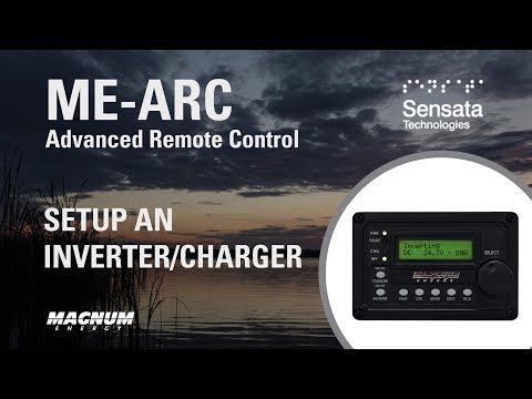
The 01 System Setup menu, reached with the Setup button, holds the basics:
- 01A System Clock — hour, minutes and AM/PM, set with the select knob.
- 01B Screen Setup — LCD brightness and contrast, plus the power-save timer that blanks the screen and LEDs after a set idle period.
- 01C Temp Display — Celsius or Fahrenheit.
Press Meter to return to the main screen. The remote is then ready for interconnections and programming.
Set up Auto Gen Start
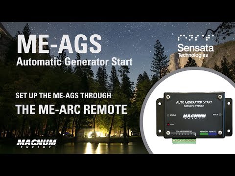
04 AGS Setup, under System Setup, defines what starts and stops the generator:
- 04A Gen Run VDC — battery voltage.
- 04B Gen Run Time — a specific time of day.
- 04C Gen Run AC Amps — unexpected load demand.
- 04D Gen Run SOC — battery state of charge.
Two of those depend on hardware: AC load demand works only with an MS-PAE, MS-PE or MSH series inverter, and state of charge needs a battery monitor kit (BMK) installed in the system.
Start an equalization charge
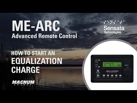
Check that your batteries can be equalized before you start. Equalization is a deliberate high-voltage charge that de-sulfates lead-acid batteries. On anything other than liquid lead-acid — and on some AGM types — it can cause permanent damage. Confirm with your battery manufacturer first.
Then, before starting: top the batteries up with distilled water, make sure the bank is well ventilated (the higher charge causes gassing), and disconnect the DC and AC loads so nothing is damaged and the AC source can put everything into the batteries.
- Program your equalization setpoints as part of the charger setup.
- Get the inverter into Float or Full charge — equalization cannot start from any other state.
- Press and hold the Charger On/Off button for 7 to 10 seconds. The status changes from Float to Equalizing.
- Press Meter to return to the main screen.
The system drops back to Float on its own once it has equalized for the time you programmed.
Guides for the
ME-RC standard remote
The standard remote, with a two-line display and a select knob you turn to reach each numbered setting. These guides were recorded on revisions 2.8 and 2.9.
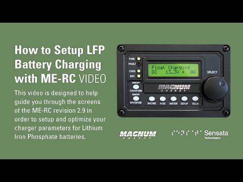
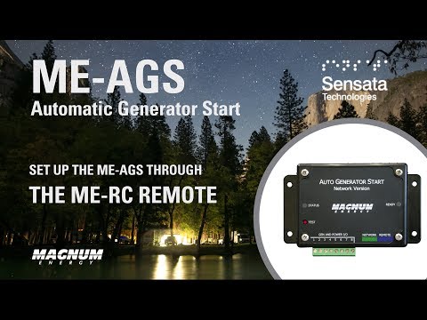
Set up charging for lithium (LFP) batteries
- From the main screen, press Setup.
- Turn the select knob to 04 Battery Type and press Select. Choose LFP — the pre-programmed lithium iron phosphate profile. (CC/CV engages constant-current/constant-voltage charging instead, and Custom lets you dial the voltages in by hand.) Press Select to lock it in.
- Turn the knob counter-clockwise to 03 Absorb Time and press Select. Set the hours your bank needs to reach a full charge — the default is 1.5. If you are not sure, your battery manufacturer or installer is the one to ask.
- Turn counter-clockwise to 02 LowBattCutOut and press Select. Lithium holds its voltage far longer than lead-acid, so it needs to cut out higher: at least 11 V on a 12 V system, 22 V on 24 V, or 44 V on 48 V — more if your battery manufacturer recommends it. Press Select to save.
- Press Meter to return to the main screen.
Set up Auto Gen Start
The AGS menu sets when the generator runs:
- 03 Run Time Hour — how long it runs once started.
- 04 Start Temp F — the inside temperature that starts it.
- 05 Start Volts — the battery voltage that starts it.
- 07 Quiet Time — a part of the day it must not run. Set the current time first. This is what keeps the generator from starting in the middle of the night.
With those programmed, 01 AGS Control turns it on — either Enable, or Enable with Quiet Time.
Brochures and dealer files
Library
The material that belongs to no single product. Manuals and spec sheets sit on the product they describe; what is collected here is the range brochures, the remote compatibility matrices, and — for authorized dealers — the service library.
AGS wiring
Diagrams
One-page wiring diagrams for connecting an Auto Gen Start to a generator. Check your relay timing first — the sequence changed across AGS revisions, and every diagram below assumes you already know which one you have.
| Your AGS revision | Where the timing sequence is |
|---|---|
| ME-AGS-N, Rev 5.0 and later | ME-AGS-N owner’s manual — see the relay timing appendix |
| ME-AGS-N and ME-AGS-S, before Rev 4.1 | Relay timing table, pre-Rev 4.1 |
| ME-AGS-N and ME-AGS-S, Rev 4.1 and 4.2 | Relay timing table, Rev 4.1 and 4.2 (3 relays) |
| ME-AGS-S, Rev 5.0 and later | ME-AGS-S owner’s manual — see the relay timing appendix |
Determine your ME-AGS revision first — the relay timing of your unit may differ from what the diagrams below show.
No rows match that search.
Archive documents for generators supported at the time of publication; revision dates run from 2007 to 2019. Confirm against your generator’s own documentation before wiring.
Brochures · Compatibility · Tech notes
Documents
Owner’s manuals and spec sheets live on the product they belong to — open a product and its documents are listed there. What follows is the material that belongs to no single product: the range brochures and catalogs, and the matrices that say which inverters a given remote firmware supports.
The technical notes that belong to no single product are here too.
Superseded revisions and discontinued ranges are not listed. Retail price sheets are deliberately not published here — contact your distributor for current pricing.
Check the firmware version on your remote before picking a row — the supported list changed between revisions.
| Document | What it covers |
|---|---|
| Aftermarket 50A installation | Fitting a 50A inverter charger to an existing coach |
| Battery temperature compensation | Float charge voltage against battery temperature, 12V |
| Inverter hi-pot procedure | High-potential testing for RV and coach manufacturers |
| Replacing a Freedom 3000 | Swapping a Freedom 3000 for a Magnum inverter |
| Router and remote comparison | Which router and remote pair with which inverter | PN 64-0675 Rev C |
| Series stacking diagrams | Wiring two inverters in series | AD-0001 |
| Wiring a remote to a 9V battery | Powering a remote from a 9V battery for display use |
Cable and fuse sizing
Reference tables
Conductor and fuse sizing for a 12VDC installation, by load and by cable run. Size for the longest run you actually have, not the shortest — the tables step up a gauge for a reason.
| Wattage | Min/max fuse (amps) | 1-10 ft. (AWG) | 11-15 ft. (AWG) | 16-20 ft. (AWG) |
|---|---|---|---|---|
| 350 | 35/50 | 8 | 6 | 6 |
| 400 | 40/60 | 8 | 6 | 4 |
| 600 | 60/90 | 6 | 4 | 2 |
| 700 | 70/100 | 6 | 4 | 2 |
| 800 | 80/120 | 4 | 2 | 2 |
| 1000 | 100/150 | 4 | 2 | 1 |
| 1200 | 120/180 | 2 | 1 | 2/0 |
| 1500 | 150/225 | 2 | 1/0 | 2/0 |
| 1600 | 160/240 | 2 | 1/0 | 2/0 |
| 1800 | 180/270 | 1/0 | 2/0 | 3/0 |
| 2000 | 200/300 | 1/0 | 2/0 | 3/0 |
| 2400 | 240/360 | 1/0 | 2/0 | 4/0 |
| 2500 | 250/375 | 1/0 | 3/0 | 4/0 |
| 3000 | 300/450 | 2/0 | 3/0 | NR |
| 3600 | 360/540 | 4/0 | 4/0 | NR |
Connecting an inverter or inverter charger to starting batteries. NR = not recommended at that run length.
| Alternator output (amperes) | 1-10 ft. (SGX AWG) | 11-15 ft. (SGX AWG) | 16-20 ft. (SGX AWG) |
|---|---|---|---|
| 100 | 4 | 2 | 1 |
| 140 | 2 | 1 | 1/0 |
| 150 | 2 | 1 | 2/0 |
| 200 | 1 | 2/0 | 3/0 |
| 230 | 1/0 | 2/0 | 4/0 |
| 250 | 1/0 | 3/0 | 4/0 |
Connecting starting batteries to auxiliary batteries.