DMX Power Catalog
Power inverter installation
Mounting, fusing and cabling a DC-to-AC inverter on a service vehicle, to NFPA, NEC and SAE practice.
Before you start
Why the method matters
- NEC
- NFPA
- SAE
A successful installation depends mainly on the methods and materials used. Low DC input voltage inverters — 12 or 24 volts — draw very high DC currents: to deliver 15 amps at 120 VAC (1,800 watts) from a 12 volt battery, the DC current approaches 180 amps. Supplying that safely and efficiently is what the rest of this guide is about.
It assumes the three system components — inverter, battery and alternator — are already chosen. Wiring follows the standards and recommended practice of:
- National Fire Protection Association (NFPA)
- National Electrical Code Handbook — NEC 96
- Society of Automotive Engineers (SAE)
- SAE Handbook, volumes 1–4
Not yet sized the inverter? Introduction to mobile power inverters covers choosing one.
System limits
Using the existing alternator and battery
Most utility vehicles carry a 100–130 amp alternator with one or two group-27 batteries. That alternator cannot sustain a continuous full-load demand above about 50 amps — but most tool use is intermittent, and between bursts it keeps up and recharges the battery. Inverters up to 2,300 watts have been installed successfully on trucks of that spec.
A smaller 1,100 watt installation in a van or light truck needs:
- an alternator rated at least 85 amps;
- a deep-cycle battery, group 27 or larger;
- 2 gauge cable from inverter to battery, up to 15 feet one way.
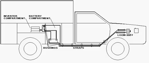
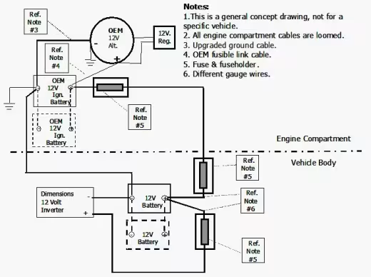
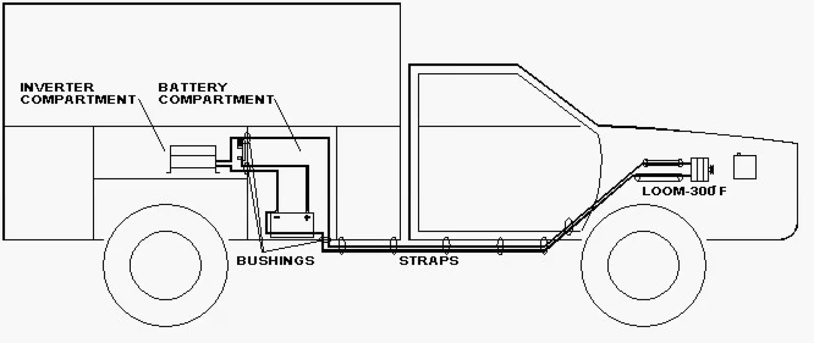
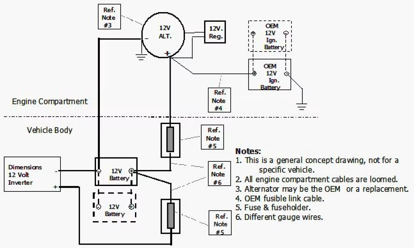
Above these ratings, or where more continuous power is needed, install a battery pack as close to the inverter as possible and upgrade the alternator. Figure 1 shows the general cable routing.
Step 1
Siting and mounting the inverter
An inverter is an electronic device and is sensitive to its surroundings. Temperature extremes, moisture and airborne contamination — drawn in whenever the cooling fan runs — all shorten its life.
Avoid mounting it under the hood, on the floor above the exhaust system, or in a sealed area where moisture can condense. The ideal compartment is clean, dry, cool and ventilated.
It must not share a space with combustible fuel vapours — switching components can ignite them — nor with corrosive battery fumes.
- Bolt the inverter securely to a platform or bulkhead.
- Leave at least one inch of clearance all round, and especially above, so warm air can escape.
- Keep the face and the large DC cable entry visible and reachable — you will need them for wiring, ground-fault testing and reading the status lights.
Step 2
Fuse holders
- NEC
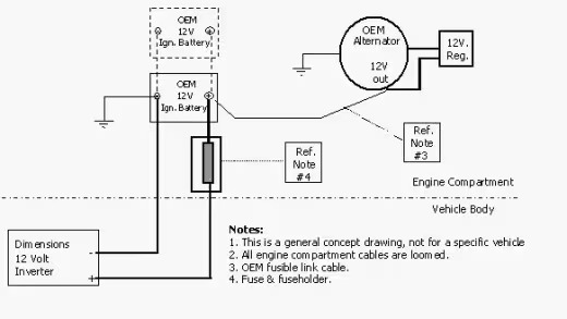
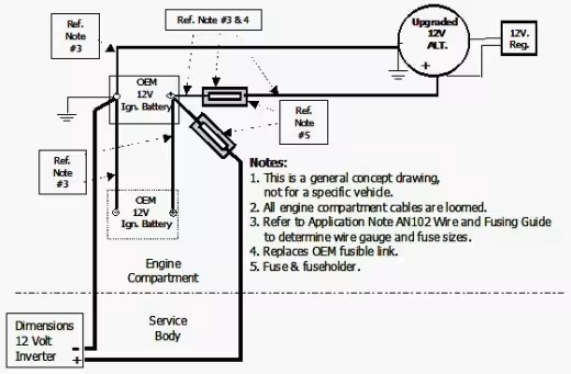
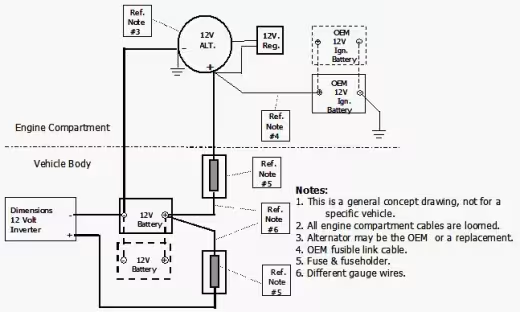
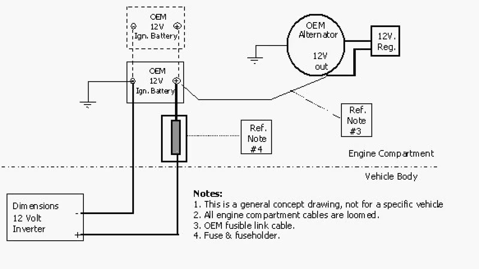
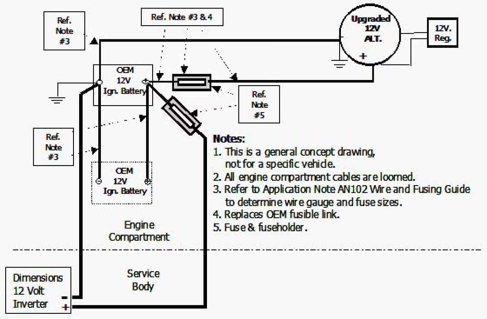
All wiring from a battery must be protected by the proper size fuse, and every fuse and holder must sit within 18 inches of the battery — see Figures 2 through 5. (Ref: 1996 NEC article 551-10(e)(4).)
Extra holders may be needed if the inverter connects to the engine battery rather than the alternator, or if the under-hood wiring is upgraded. The auxiliary battery fuse protects both the cables to the inverter and those to the alternator; a direct connection to the engine battery needs its own holder mounted there.
Never install these holders in an airtight battery compartment — the explosion hazard is the same one described below.
- Mount each holder within 18 inches of its battery, somewhere reachable.
- Label the fuse rating beside its holder.
- Do not fit the fuses until all wiring is complete.
For gauge and fuse sizing, use the 12VDC cable and fuse guide.
Step 3
The battery compartment
Assume hydrogen is evolving from the battery continuously. The battery area must be vapour-tight to the vehicle interior and vented directly outside. Hydrogen is lighter than air and escapes through openings at the top; openings at the bottom let fresh air in. Fit several vent plugs within one inch of both the top and the bottom.
The battery must not share an airtight space with spark-producing equipment — the inverter or the fuses — which could ignite that hydrogen.
- Mount the battery with hold-downs, a tray or a box, on a level clean surface. Boxes must be the vented type.
- Leave space around and above it for ventilation, inspection and maintenance.
- Secure it so it cannot move more than one inch in any direction, even inverted.
- For large banks, fabricate an angle-iron frame with a protective cover.
Step 4
DC wiring
- SAE
Use SGX cable. SGX cross-linked polyurethane meets SAE J-1127 and vehicle manufacturer requirements, and its insulation meets that standard’s 125°C rating. Complete cable assemblies with fuses and holders are available — ask us. Size it from the 12VDC cable and fuse guide.
Pick the cabling diagram that matches the installation:
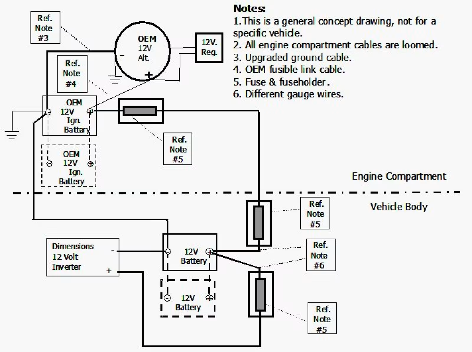
- Figure 2 and Figure 3 — 1,000 watts or less, no auxiliary battery, with the OEM alternator and with an upgraded one.
- Figure 4 — larger inverters with one or more auxiliary batteries. This is the preferred method.
- Figure 5 — as Figure 4, but cabled back to the OEM battery.
Routing the cables — run both charging cables directly to the alternator, as Figure 1 shows. Never use the vehicle chassis as a conductor.
- Through a partition, fit a protective rubber grommet against abrasion and seal the excess opening with caulk to keep fumes out.
- Under the vehicle, clamp the cables every 18 inches so nothing can snag, and keep them away from the drive shaft, exhaust and fuel line.
- In the engine compartment, use high-temperature (300°C) loom and take the coolest route available.
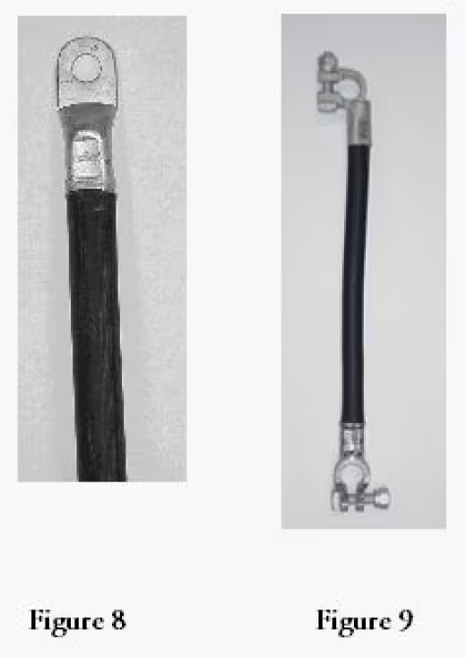
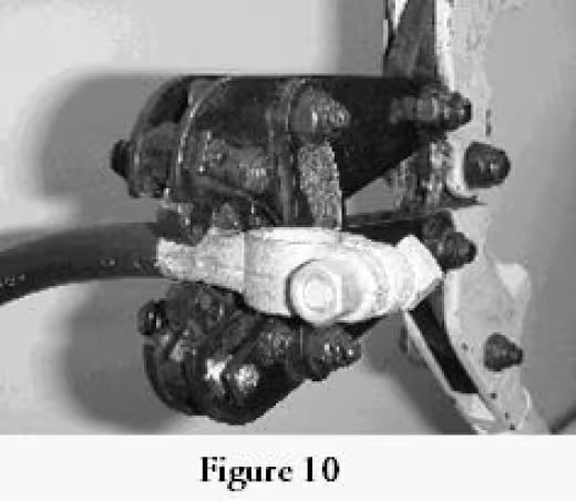
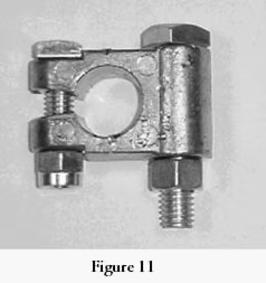
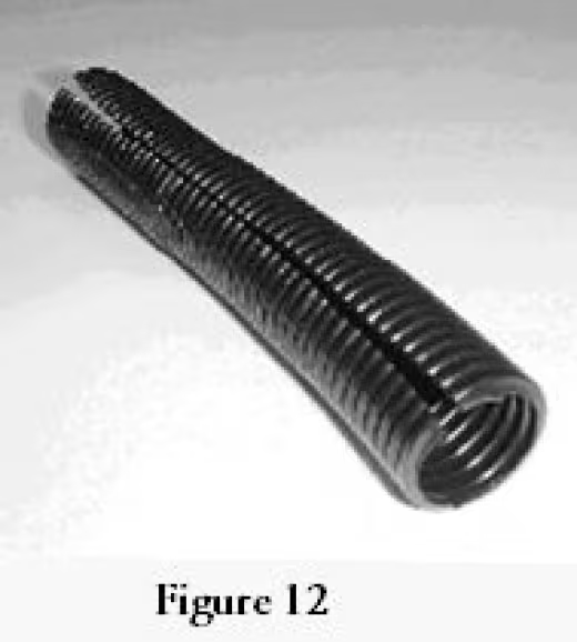
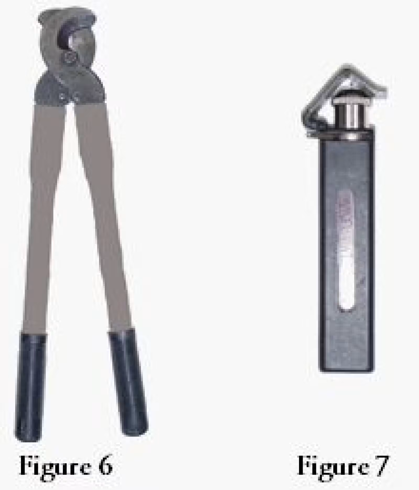
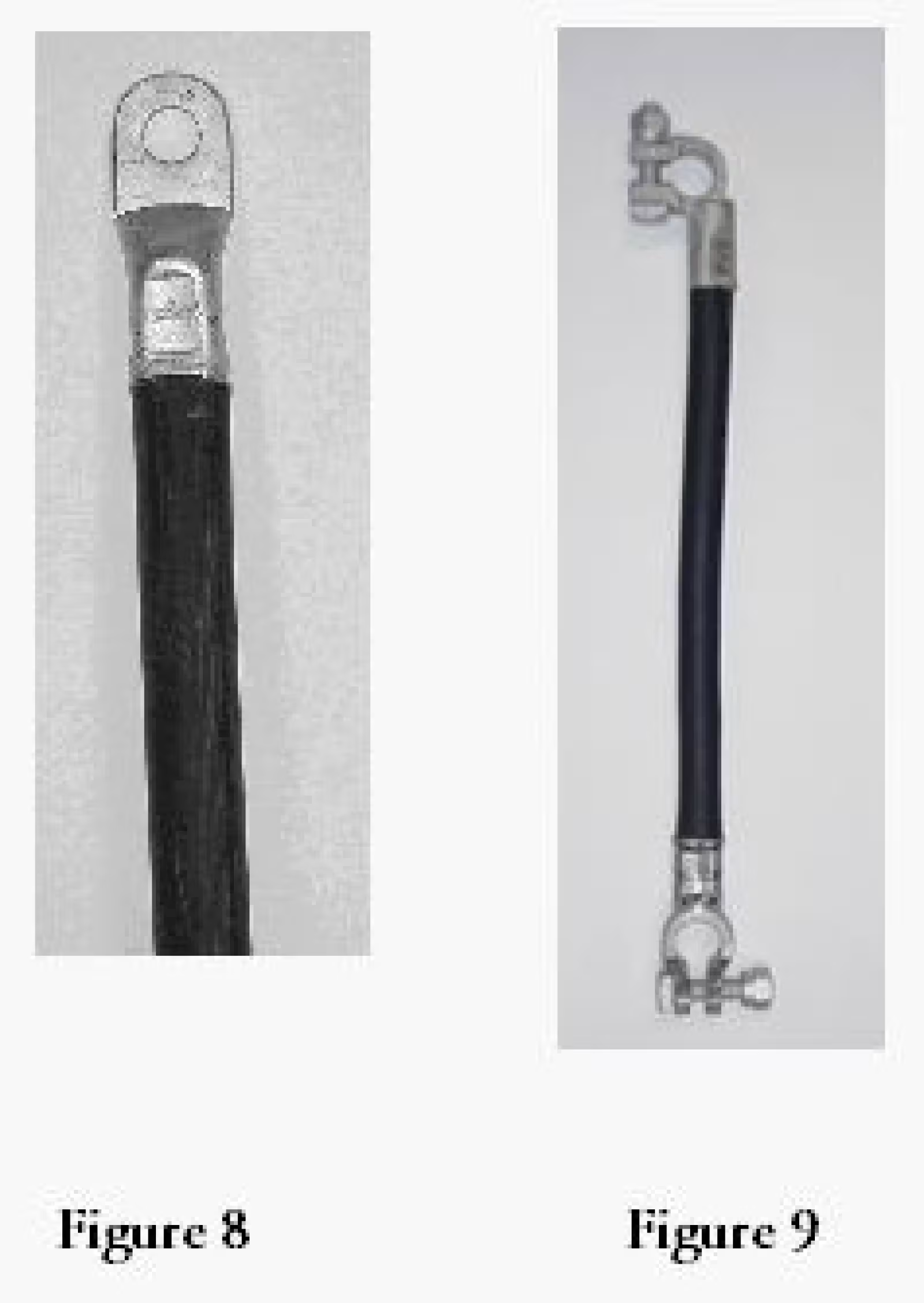
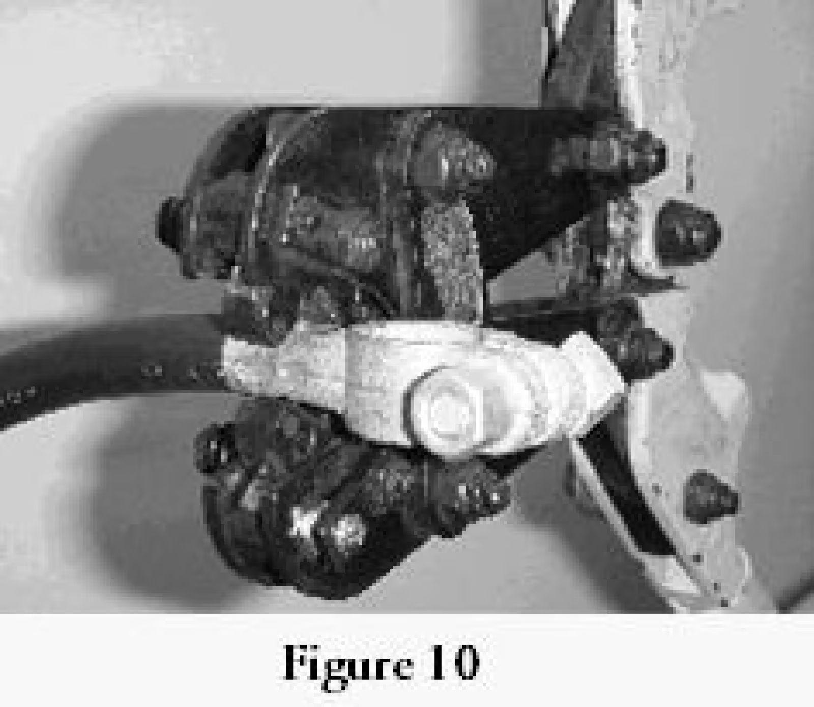
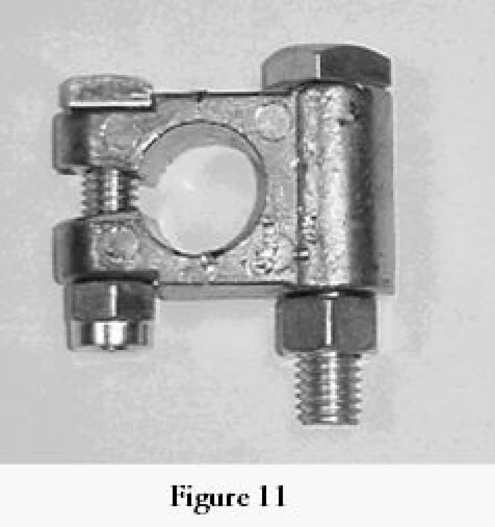
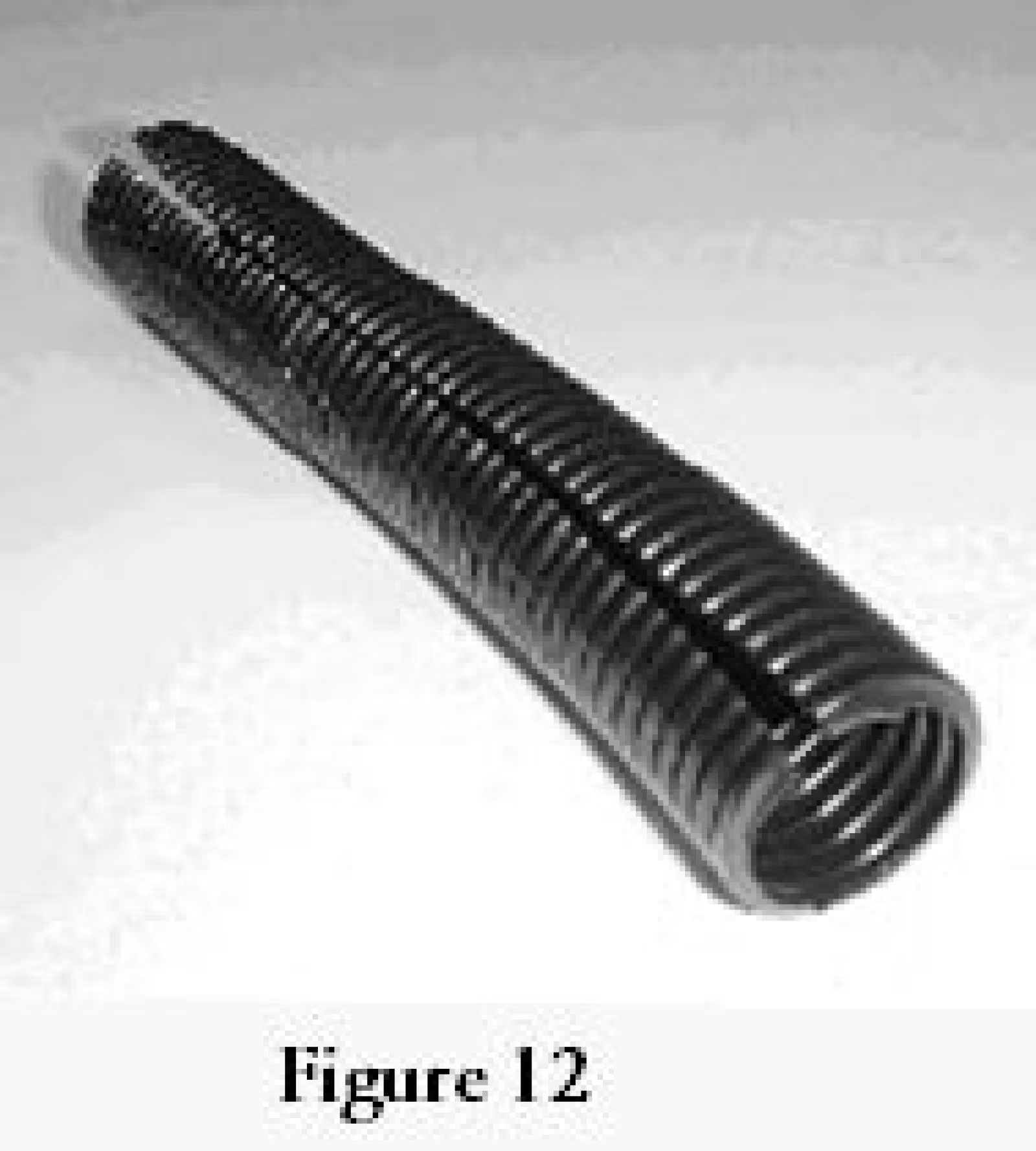
Terminating the cable needs the right tools — see Figures 6 and 7 — and a properly crimped, insulated lug, shown in Figures 8 through 12.
Step 5
AC wiring
- UL
AC wiring must be stranded copper for vibration resistance, protected by conduit, and routed close to the frame. Tape over the wire nuts at terminations — vibration loosens them.
- Up to 10 AWG, use boat and truck cable: UL listed, meets DOT specification, stranded copper, 16–10 AWG, non-metallic.
- Above 10 AWG, use type NM-B cable or individual building wire: UL listed, stranded copper, non-metallic.
- Use conduit — rigid electrical metallic tubing, or rigid PVC.
- Use junction and outlet boxes matched to the conduit system.
- Bond it. Run a #8 stranded copper wire from the bonding lug on the inverter chassis to the vehicle chassis. Both connections must be tight against bare metal — use star washers to bite through paint and corrosion.
Bonding is a safety requirement, and it also reduces radio interference. The DMX Power inverter is UL listed and its DC input connections are isolated from the chassis.
Diagrams and photographs
References
Every figure this guide refers to. Select one to open the set at full size.